Change the Display of Models
Use different render modes, such as shaded display and the display as wire frame. Also, you may adjust the display, e.g. show the not connected edges of a model.
 Change the Render Mode of Models
Change the Render Mode of Models
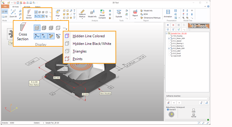
The functions to change the render mode of models are located in the Display group of the 3D-Mode tab.
 Shaded Display
Display all parts shaded.
 Shaded with Edges
Display all parts shaded with black edges.
 Shaded Mesh
Display all parts as shaded mesh.
 Wire Frame Display
Display all parts as wire frame.
 Hidden Line Colored Display
Display all parts as hidden line graphics with lines in the color of the parts.
 Hidden Line Black/White Display
Display all parts as hidden line graphics with black lines on a white background.
 Mesh
Mesh
Display all parts as mesh.
 Vertices
Display all parts as vertices.
 Tip
Tip
Right-click on parts to display them in an individual shade mode.
 Notes
Notes
- To change the number of edges displayed with the render modes Shaded with Edges, Wire Frame, and Hidden Line, use Change Wire Frame Angle in the Options tab.
- When opening CAD files (STEP, IGES, CATIA, Pro/E, etc.), the face boundaries of models can be loaded and displayed as curves. To do so, activate the Load face boundaries as curves option in the Import Settings.
Adjust the Display
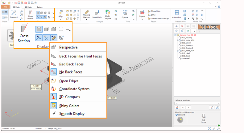
The functions to adjust the display are located in the Display group of the 3D-Mode tab.
 Show Curves
Show the 3D curves of the models.
Note
When opening CAD files (STEP, IGES, CATIA, Pro/E, etc.), the face boundaries of models can be loaded and displayed as curves. To do so, activate the Load face boundaries as curves option in the Import Settings.
 Show Reference Points
Show the reference points that are present in the models.
 Show Dimensions and Markups
Show the 3D dimensions and markups created with the Measure and Markup tool.
 Show Exploded
Show the models exploded. Use the Explode tool to create explosion data for your models.
 Perspective View
Use perspective view instead of orthogonal view.
 Display Back Faces Like Front Faces
Display shaded faces with same colored back faces.
 Display Red Back Faces
Display shaded faces with red back faces.
 Display No Back Faces
Display shaded faces without back faces. This speeds up the display.
Note
Especially with STL files, it is possible that front faces are inverted. In this case, the faces cannot be seen with the default setting Display No Back Faces. Change the display of the back faces to Display Back Faces Like Front Faces to solve the problem.
 Show PMI
Show the Product Manufacturing Information present in the models.
 Show Open Edges
Show the edges of planes that are not connected in yellow.
 Show Coordinate System
Show the absolute coordinate system as x-, y- and z-axis starting at (0,0,0).
 3D-Compass
Show the x-, y- and z-axis as orientation in the lower left corner of the display.
 Shiny Colors
Display surfaces with bright light reflections that give the model a shiny look and increase the 3D-effect. Switch off the shiny colors, e.g. for a more technical viewing. The intensity of the reflection can be set in the Preferences:
Options tab > Preferences button > 3D-color
Smooth Display
Display shaded faces smoothed based on their smooth vectors. If smoothing is not satisfactory, use Adjust Smoothing in the Options tab to calculate new smooth vectors.