 Cross Section
Use the Cross Section tool to view the inner structure of a model as well as selecting and measuring parts that are difficult to access.
To create cross sections in 3D-Mode, click Cross Section in the Display group.

After activating the tool, the model will be displayed sectioned. The section settings are shown in the top of the display. The cross section controls are shown in the display in front of the model.
 Position and Align the Cross Section
Using the Cross Section Controls
Position and Align the Cross Section
Choose cross section plane
To choose one of the three standard planes as cross section plane, do one of the following:
- In the section settings choose one of the 3 standard planes:
 XY-Plane
 XZ-Plane
 YZ-Plane
 - Click one of the transparent planes of the cross section controls.
Pick cross section position on the model
To position and align the cross section by mouse click on the model the cross section settings offer the following:
- Set cross section position
Select Set cross section position and move the mouse pointer over the model. Points to set the cross section plane will be highlighted in blue. Click to move the cross section plane to the point.
 - Set cross section position perpendicular to curve/edge
Select Set cross section position perpendicular to curve/edge and move the mouse pointer over the model. Curves/edges to set the cross section plane will be highlighted in blue. Click to move the cross section plane to the middle of the curve/edge and align it perpendicular to the curve/edge.
 - Set cross section position parallel to plane
Select Set cross section position parallel to plane and move the mouse pointer over the model.
Model planes to set the cross section plane will be highlighted in blue. Click to align the cross section plane parallel to the model plane. - Set cross section position to center of a circle
Select Set cross section position to center of a circle and move the mouse pointer over the model. Centers of circles to set the cross section plane will be highlighted in blue. Click to move the cross section plane to the center of the circle.
Move the section plane
To move the section plane, do one of the following:
- Move the slider in the section settings.
- Enter a value in box above the slider.
- Click the small buttons left and right of the slider.
The << and >> buttons move the section plane in big steps.
The < and > buttons move the section plane in small steps. - In the cross section controls click the shaft of the red arrow, hold down the mouse button and drag the section plane to the wanted position.
Rotate the section plane
To rotate the section plane around the x, y, or z-axis, do one of the following:
- Drag the sliders in the section settings.
- Enter values into the boxes behind the sliders.
Switch the displayed side of the model
To display a different side of the sectioned model, do one of the following:
- In the section settings, choose one of the options Side 1, Side 2, or Cross section. Cross section will show only the cross section and hide both sides of the model.
- In the cross section controls, click the head of the red arrow to switch between Side 1 and Side 2.
 Tips
Tips
- Use cross sections with the Measure/Markup tool to measure inaccessible parts. Also, the points and edges of the section line can be measured.
- Cross sections can be saved as a Custom Views. All cross section settings will be saved, including parts excluded from the cross section.
Using the Cross Section Controls
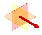
To activate the cross section controls, select Show cross section controls from the  Cross section options.
Move the section plane
To move the section plane, click the shaft of the red arrow, hold down the mouse button and drag the section plane to the wanted position.
Switch the displayed side of the model
To display a different side of the sectioned model, click the head of the red arrow to switch between Side 1 and Side 2.
Choose cross section plane
To choose one of the three standard planes as cross section plane, click one of the transparent planes of the cross section controls
Display Parts Uncut
To display a part uncut, right-click the part on the model or in the model tree and choose  Cross section on/off . To display a part cut again, use Cross section on/off once more.
To display all parts cut again, select Show all parts sectioned from the Cross section options.
Cross Section Options
Show all parts sectioned
Use the cross section on all parts. Uncut parts will be sectioned again.
 Export cross section as DXF
Save the current section line as a 2D DXF file.
The Transform to xy-plane option transforms the section line to the standard XY-plane, so the cross section will be shown accurately in 2D-CAD programs. Deselect this option to keep the 3D orientation of the section plane for a 3D-CAD program.
Show cross section controls
Show the 3D cross section controls. The cross section controls let you move the section plane, switch the displayed side of the model, and change the section plane.
Fill section
Fill the cross section using the colors of the cut parts.
Section line
Show/hide the section line. Change the color of the line in the 3D-Tool preferences:
Options tab > Preferences group > Preferences > 3D section