 Model Compare (not available with the Free Viewer and in EXE files)
Use the Model Compare tool to graphically highlight the differences between two models.
The Model Compare tool is located in the Analysis group of the 3D Mode tab.

Load and Select Models
Load two or more models that you want to compare. If the file names are identical, the models are renamed automatically.
After the import, the models are listed in the model tree and overlap in the display.
Now activate the Model compare tool.
Select the two model you want to compare from the two drop down list, located at the top of the tool. If only two models are loaded, they are selected automatically.
 Note
Note
The 3D-Tool Model Compare is a graphical/visual comparison by dyeing the models in different colors and then laying one model on top of the other. Differences located inside the models can only by using cross section or by hiding parts.
 Compare Models in Solid Mode
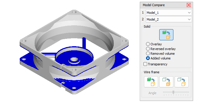
In this mode the models to be compared are put on top of each other in solid render mode.
Consecutively use multiple or all of the following options to find all differences. Especially useful is switching between Overlay and Reversed overlay as well as between Removed material and Added material.
Overlay
Display the two models in different colors and superimpose model 1 over model 2. The two models differ in all places where you can see the color of model 2.
Reversed overlay
Display the two models in different color and superimpose model 2 over model 1. The two models differ in all places where you can see the color of model 1.
Removed material
Highlight material that does NOT exist in model 2.
Added Material
Highlight material that does ONLY exist in model 2.
Transparency
Display the top model color transparent so differences inside of parts can be seen more easily.
 Tip:
Tip:
Activate the  Cross Section tool and move the section through the models to find the difference inside of models and parts. The section plane is always filled with the color of the cut material and letting you see differences by the inconsistency of the section plane color.
Wire Frame

 Compare model 1 with model 2 as wire frame
Display model 1 solid and superimpose model 2 as wire frame over model 1. The two models differ in all places where you can only see the wires of model 2 or only the solid faces of model 1.
 Reverse compare - Compare model 2 with model 1 as wire frame
Display model 2 solid and superimpose model 1 as wire frame over model 2. The two models differ in all places where you can only see the wires of model 1 or only the solid faces of model 2.
 Compare both models as wire frame
Display both models as wire frame and superimpose model 2 over model 1. The two models differ in all places where you can see wires in the color of model 1.
Wire frame angle
Change the resolution of the wire frame. Move the slider left to lower the wire frame angle and to get a denser wire frame. Move the slider right to increase the wire frame angle and to get a lighter wire frame.
Note
The wire frame is based on the edges of the triangles that make up the model in the viewer. If you open models using different import settings (Chord height, Angle tolerance) the models may show deviations that do not exist.